
Table of Contents
- Safety First: Electrical Hazards in Older Farm Irrigation Systems
- Diagnosing Whether the Fault Is Electrical or Mechanical
- Irrigation Pump Electrical Troubleshooting: Power Supply and Fuses
- Testing Wiring, Wire Splices, and Corrosion
- Center Pivot Electrical Troubleshooting: Controllers and Decoders
- Irrigation Control Panel Troubleshooting: Solenoids and Valves
- Irrigation Electrical Maintenance Checklist: Preventing Intermittent Faults
- When to Call a Licensed Electrician
- Frequently Asked Questions
Last Updated: October 19, 2026
Safety First: Electrical Hazards in Older Farm Irrigation Systems
Troubleshooting old farm irrigation electrical systems requires caution. Older installations often lack modern safety features.
Before you touch anything, cut power at the main disconnect. Assume all wires are live until proven otherwise.
Older farm systems commonly have exposed wiring, corroded connections, and inadequate grounding, so livestock and equipment can contact energized components.
If you’re unsure about any step, stop and call a licensed electrician.
Key safety rules for old farm systems:
- Turn off power before any inspection or test
- Use a multimeter to verify power is off
- Check for water intrusion at all connection points
Older irrigation controllers often use 24-volt transformer circuits that can fail silently. A failed transformer won’t trip a breaker; it just stops delivering signal to solenoid valves. The system appears dead, but the main power remains energized. Always verify power status with a multimeter, not just by testing the control circuit.
Diagnosing Whether the Fault Is Electrical or Mechanical
The first step in troubleshooting old farm irrigation electrical systems is determining whether the fault is electrical or mechanical, which saves time and prevents unnecessary part replacement.
Signs of an electrical problem
Electrical faults typically show these symptoms:
- Controller displays no lights or error codes
- Solenoid valves don’t click or buzz when triggered
- No voltage at the pump motor terminals
An electrical problem stops signal flow or power delivery while the mechanical side (pump, valves, pipes) works fine. Test for voltage at key points: controller input, transformer output, solenoid coil terminals. If voltage is missing where it should be present, you have an electrical fault.
Signs of a mechanical problem
Mechanical failures produce different symptoms:
- Controller sends signal but solenoid doesn’t respond
- Water pressure is low or absent
- Valves leak water continuously
A mechanical problem means power and signal reach the device, but the device doesn’t work: the pump spins but a bearing is worn, or the solenoid valve receives 24 volts but the plunger is stuck. To confirm, apply voltage directly to a solenoid coil. If it clicks, the coil is good and the problem is mechanical; if it doesn’t click, the coil is open or shorted, an electrical fault.
Many farmers assume “the system is down” means the pump failed. In reality, 70% of irrigation downtime comes from electrical signal loss, not mechanical failure. Check power and signal first. The pump is usually fine.
Irrigation Pump Electrical Troubleshooting: Power Supply and Fuses
Troubleshooting old farm irrigation electrical systems at the pump level starts with power verification.
Checking the power supply
Locate the main disconnect switch near the pump or at the control panel. This is where utility power enters the farm system.
- Verify the disconnect is in the OFF position
- Use a multimeter set to AC voltage (typically 240V or 480V for farm pumps)
- Place one probe on each terminal of the main disconnect
- Reading should be zero volts with the switch OFF
- If voltage is present when OFF, the disconnect is faulty; do not proceed
- Turn the disconnect ON
- Measure voltage again; you should see the full supply voltage
- If voltage is low (more than 10% below rated), check the utility line or transformer
Old farm systems often have undersized or corroded service entrance conductors. A pump rated for 240V that only receives 210V will draw extra current and overheat.
Measure voltage at the pump terminals, not just the disconnect: a long run of corroded wire can lose significant voltage, meaning the feeder wire is the problem.
Inspecting fuses and transformers
A blown fuse indicates either a fault or an undersized fuse.
- Turn OFF the main disconnect
- Locate the fuse holder (usually a cartridge type on older systems)
- Remove the fuse carefully
- Visually inspect the fuse element; it should be intact
- A blackened or broken element indicates a blown fuse
- Check the fuse amperage rating (printed on the cartridge)
- Replace with an identical amperage fuse only
- Never use a higher-rated fuse to “fix” repeated blowing
If a fuse blows immediately after replacement, a short circuit exists. Do not keep replacing fuses. Find and repair the short.
Transformers step voltage down from the main supply (usually 240V or 480V) to 24V for the controller and solenoids. Older transformers fail silently.
Test transformer output with a multimeter:
- Verify primary power is ON (measure input voltage)
- Set multimeter to AC voltage
- Measure across the transformer secondary terminals
- Should read 24V AC (or whatever the transformer rating states)
- If zero volts, the transformer is open; it must be replaced
- If voltage is present but solenoids don’t respond, test the solenoid coil directly
A transformer that reads 24V at no load but drops to 8V when the solenoid is energized indicates a weak transformer nearing failure. Replace it before it fails completely.
Testing Wiring, Wire Splices, and Corrosion
Field wiring carries power from the pump or controller to solenoid valves across the irrigation zone, exposed to sun, rain, freezing, and soil chemicals. Corrosion and water intrusion are the leading causes of intermittent faults in old farm systems.
Visual inspection of field wiring
Start with your eyes before using any test equipment.
- Walk the field wiring route from the controller to each solenoid valve
- Look for cracked or brittle insulation; it should be flexible, not chalky
- Check for exposed copper or aluminum conductors
- Inspect all wire splices (connection points where wires join)
- Look for water pooling near junction boxes or valve terminals
- Note any burn marks or discoloration on the insulation
- Check for rodent damage (chewed insulation is common in farm settings)
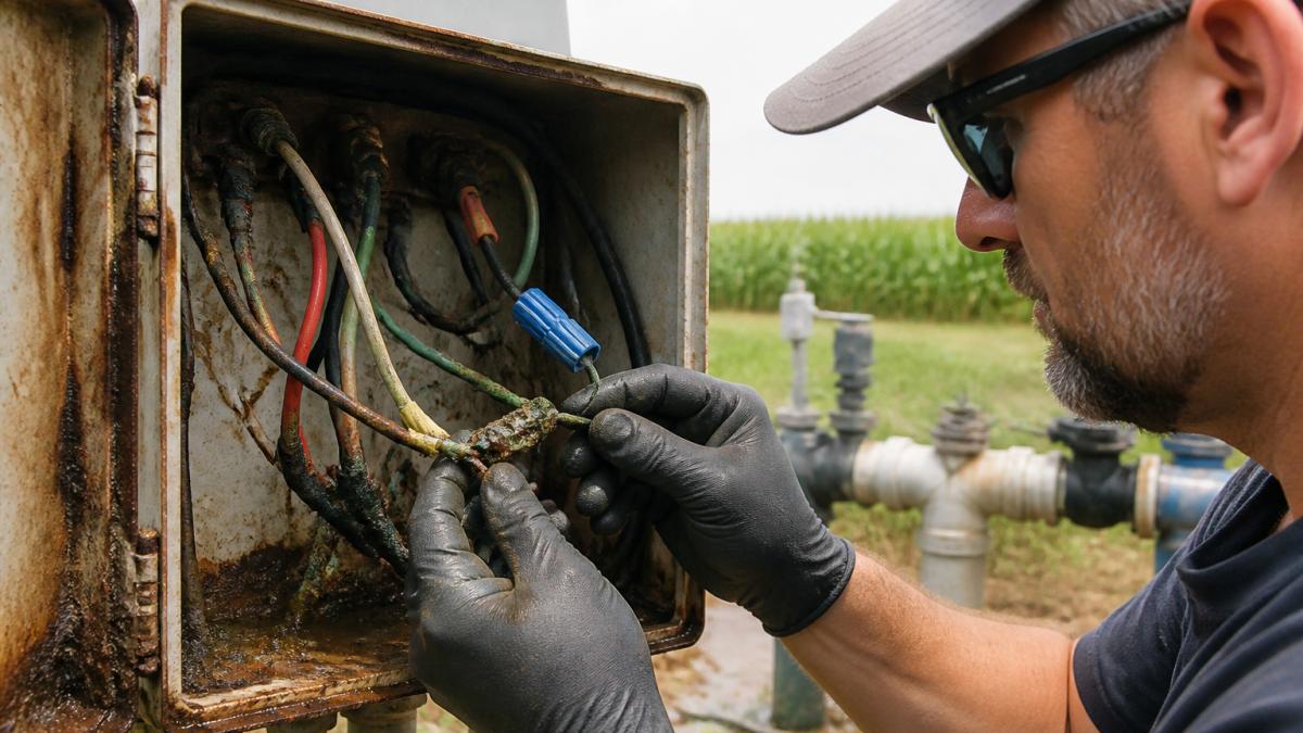
Old splices often use wire nuts or simple twist connections that corrode rapidly in wet soil; replace them with waterproof connectors rated for outdoor use.
Measuring electrical resistance and continuity
Resistance testing detects broken wires, corroded connections, and damaged insulation.
- Turn OFF all power to the circuit being tested
- Set the multimeter to resistance mode (ohms, usually marked with the Ω symbol)
- Disconnect one end of the wire from its terminal
- Place one probe at each end of the wire
- The reading should be near zero ohms (0.1 to 1 ohm for a good wire)
- A reading of 10+ ohms indicates corrosion or a partial break
- Infinite resistance (no reading) means the wire is open (completely broken)
For field wiring runs over 30 meters long, expect slightly higher resistance (1-3 ohms). Anything above 5 ohms suggests corrosion that needs attention.
Test continuity by checking resistance through a complete circuit. For a solenoid valve circuit:
- Disconnect the solenoid coil leads from the controller
- Measure resistance from the controller terminal to the solenoid terminal and back
- Should be a complete loop with low resistance
- If resistance is very high or infinite, the wire is broken or the splice is corroded
Intermittent faults often occur when resistance is high but not infinite. The connection works sometimes and fails other times. Moisture, temperature changes, and load variations cause intermittent operation.
A solenoid that clicks occasionally but doesn’t hold the valve open usually indicates high resistance in the coil circuit. The control signal reaches the solenoid, but the voltage is too low to maintain the magnetic hold. Check all wire splices and clean corroded terminals.
Center Pivot Electrical Troubleshooting: Controllers and Decoders
Modern center pivots use electronic controllers and decoder boxes to manage multiple zones. Older systems used simple timers and relays. Both can fail, but the diagnostic approach differs.
Identifying controller error codes
Electronic controllers display error codes or LED patterns when faults occur, telling you where to look.
- Note the exact LED pattern or error code displayed
- Consult the controller manual for code definitions (keep manuals on file)
- Common codes include: Low voltage, sensor fault, communication error, overload
- A low-voltage code usually means the transformer output is weak or the battery backup is dead
- A communication error indicates the decoder isn’t receiving signal from the controller
- An overload code suggests a solenoid is drawing too much current (partially shorted)
If the controller displays no lights or code, check power first: measure voltage at the controller terminals. If voltage is present but the display is dark, the controller may be failed. Many older controllers use simple mechanical timers with no error codes; if the timer doesn’t advance or the relay doesn’t click when it should, the timer mechanism is worn or the relay coil is open.
Testing signal communication and decoder faults
Decoders translate the controller signal into individual zone commands, each controlling one or two zones.
- At the controller, measure the signal voltage (usually 24V AC)
- Follow the signal wire to the decoder location
- Measure voltage at the decoder input terminals
- Should match the controller output (typically 24V AC)
- If voltage is present at the controller but missing at the decoder, the signal wire is broken
- If voltage is present at the decoder input but the zone doesn’t operate, the decoder is faulty
Decoders in older systems were often mounted directly on the solenoid valve body. Water intrusion and corrosion destroy these quickly. Replacement is usually cheaper than repair.
Test individual solenoid response by applying 24V directly across the coil terminals (power OFF first, then briefly ON).
Irrigation Control Panel Troubleshooting: Solenoids and Valves
Solenoid valves are electromagnetic switches that open and close water flow. They’re simple but fail frequently in older systems due to corrosion and water intrusion.
Testing solenoid coils with a multimeter
A solenoid coil is an electromagnet: when energized, it creates a magnetic field that pulls the valve plunger open; when de-energized, a spring closes it.
- Disconnect the solenoid coil leads from the controller wiring
- Set the multimeter to resistance mode (ohms)
- Place one probe on each solenoid terminal
- A healthy 24V solenoid reads 200-500 ohms
- A reading near zero ohms indicates a shorted coil (internal short)
- A reading of infinite ohms indicates an open coil (broken winding)
- Either condition requires coil replacement
For 120V or 240V solenoids, resistance readings are lower (20-50 ohms); consult the solenoid specifications. If the resistance reading is normal but the solenoid doesn’t click when power is applied, the problem is not the coil.
Diagnosing zone failures and valve operation
A zone that won’t open can fail for three reasons: no power to the solenoid, a faulty solenoid, or a mechanically blocked valve.
- Verify the controller is sending a signal to that zone (check for error codes or LED indication)
- Measure voltage at the solenoid terminals while the zone is commanded ON
- If voltage is present and the solenoid clicks, the valve is mechanically stuck or blocked
- If voltage is present but the solenoid doesn’t click, the coil is open or shorted
- If voltage is absent, trace back to find where signal is lost
A zone that opens but water won’t flow indicates a blocked or failed valve, mechanical, not electrical.
Intermittent zone failures usually point to a corroded connection or a partially shorted solenoid coil.
Farms with multiple zones failing intermittently should focus first on cleaning all wire splices and solenoid terminals. Corrosion causes 80% of intermittent faults in older systems. Replacement is rarely needed until cleaning fails.
Irrigation Electrical Maintenance Checklist: Preventing Intermittent Faults
Preventive maintenance stops problems before they start. Older farm irrigation electrical systems need regular attention to stay reliable.
Seasonal and routine inspection steps
Schedule inspections twice yearly: spring before irrigation season and fall after shutdown.
- Turn OFF main power before inspecting
- Walk all field wiring routes and note damage
- Check for water pooling near junction boxes
Spring inspection focus:
- Check for winter freeze damage to above-ground wiring
- Verify no rodents have damaged insulation
- Test all zone solenoids before irrigation starts
Fall inspection focus:
- Drain water from junction boxes and controller enclosures
- Apply corrosion inhibitor spray to exposed terminals
- Check transformer for signs of overheating
Environmental damage and water intrusion prevention
Water is the enemy of electrical systems. Older farm installations often lack proper enclosures.
Protective measures:
- Install weatherproof boxes around all outdoor connections
- Slope junction box lids to shed water
- Use silicone sealant around all wire entry points
Temperature extremes accelerate corrosion. In areas with freeze-thaw cycles, water trapped inside connections expands and contracts, breaking connections. Proper drainage prevents this.
Intermittent faults often occur after rain or during high humidity. If a zone fails only after wet weather, water intrusion is likely.
When to Call a Licensed Electrician
Some situations require professional expertise. Knowing when to stop and call saves money and prevents injury.
Call a licensed electrician if:
- Main power is absent or extremely low voltage (under 200V for 240V systems)
- Fuses blow repeatedly or breakers trip immediately after reset
- You find evidence of burning, melting, or charring in the control panel
Bighorn Electric’s licensed electricians have diagnosed and repaired aging farm irrigation electrical systems across Western Canada. Bighorn Electric’s services page
Professional diagnosis costs less than guessing. A licensed electrician can measure voltage, resistance, and signal flow systematically.
Troubleshooting old farm irrigation electrical systems demands patience and systematic testing.
Frequently Asked Questions
How do you know if an irrigation system has an electrical problem versus a mechanical problem?
Electrical problems typically show no power to the pump or controller, blown fuses, tripped breakers, or error codes on the control panel. Mechanical problems involve water flow issues, pressure loss, or pump noise despite power reaching the equipment. Check for power first using a multimeter; if voltage is present but the pump or zone won’t operate, the fault is likely mechanical. If there’s no voltage or the system trips immediately, focus on electrical diagnosis.
What should you check first when troubleshooting an older irrigation pump that won’t start?
Start with power supply: verify voltage at the breaker or disconnect switch using a multimeter (should match the system rating, typically 240V for farm pumps). Check that the breaker hasn’t tripped and inspect fuses for burn marks or corrosion. Look for loose connections at the disconnect and pump terminals. If power is present but the pump doesn’t start, test the capacitor (if equipped) and check for a stuck impeller or seized bearing, which are mechanical faults requiring different repairs.
Why does a center pivot stop moving even though it has power?
A powered center pivot that won’t move often has a signal or decoder fault. Check the controller display for error codes indicating communication loss. Inspect field wiring and wire splices along the pivot for corrosion, water intrusion, or broken connections. Test electrical continuity from the control panel to the decoder using a multimeter. If the decoder has no signal, the wiring between the controller and pivot motor is open or short-circuited. Verify the transformer in the control panel is supplying the correct voltage to the decoder circuit.
How often should you perform electrical maintenance on an older farm irrigation system?
Inspect your system at least twice yearly: before the irrigation season and after it ends. Check all wire splices, terminals, and connections for corrosion and water damage. Test solenoid coils and verify zone operation monthly during the season. After heavy rain or flooding, inspect field wiring immediately for water intrusion. Replace corroded fuses, tighten loose terminals, and seal junction boxes to prevent moisture entry. Regular maintenance catches intermittent faults before they cause complete system failure during critical growing periods.
0 Comments